Build Guide
Base Board
-
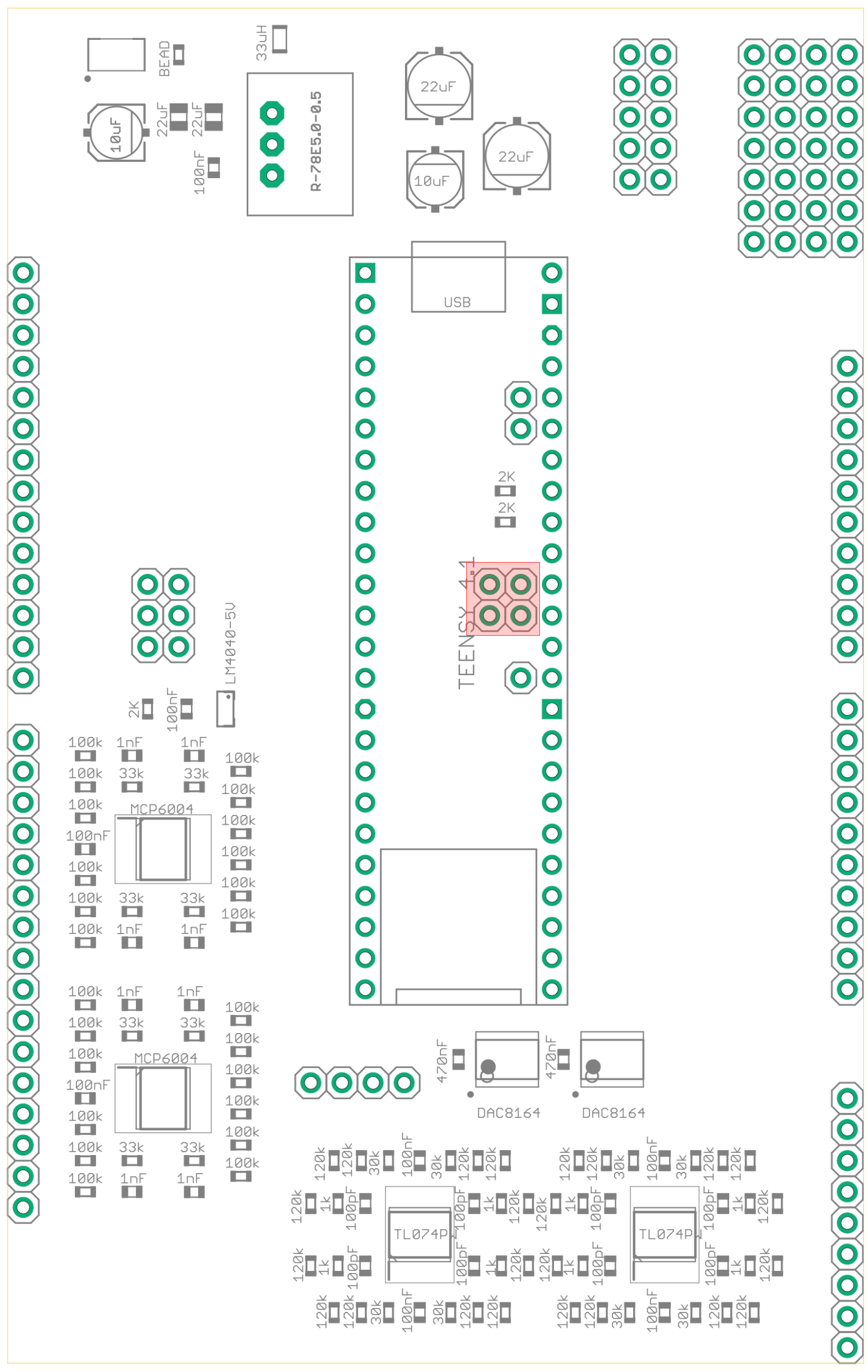
Solder surface mount components onto base board. The components highlighted in red below do NOT need to be soldered.
-
Solder the power header (male header pins).
-
Solder the teensy header (female header).
-
Solder the through hole voltage regulator.
-
Solder the male header pins on the opposite side of the board. Headers marked in red above do not need to be soldered.
Control Board
-
Solder surface mount components on the back of the control board.

-
Solder the female header rows. Headers marked in red above do not need to be soldered.
-
Use the spacers and screws to mount the OLED screen so the pins fit through the holes. Do not solder it yet.
-
Place the potentiometers, rotary encoders, and jacks onto the board but do not solder them yet.
-
Solder the controls onto the pcb.
-
Push the oled screen towards the front panel so that it is touching it, then solder the OLED pins.
Teensy
-
With a knife, cut the trace for powering via USB. Check there is no continuity with a meter.
-
Solder the PSRAM to the back of the Teensy.
-
Solder the male headers pin onto the Teensy.