Hardware
Teensy Motherboard 8CV
Motherboard for teensy containing circuits to enable the following:
- 8 CV Inputs
- 8 Potentiometer Inputs
- 8 CV Outputs using DAC8164
- 16 Digital Inputs or Outputs using MCP23S17 IO expander
Works with Teensy LC/4.0/4.1
Soldering
Depending on requirements not all of the components need to be soldered.
Do not solder both section A and B at the same time.
- A. Solder these resistors if there are 4 or less potentiometers. They connect the potentiometers directy to analog input on the Teensy.
- B. Solder the CD4051 if there are more than 4 potentiometers. They will be multiplexed to a sinlge analog input on the Teensy.
- C. 8 control voltage inputs with range -5V to 5V.
- D. IO expander providing 16 digital input or output pins.
- E. 8 control voltage outputs with a range from -5V to 5V. If only 4 outputs are required then only one of DAC8164 need to soldered.
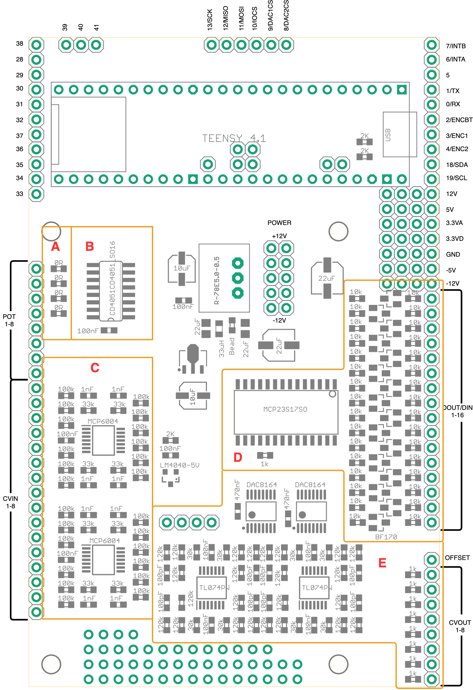
Board Pins
- POT 1-8: Potentiometer connections. Potentiometers should output a voltage from 0V to 3.3V. Values higher will damage the Teensy.
- CVIN 1-8: 8 Control Voltage inputs which accept a range from -5V to 5V. Each input has 2 pins which are summed together, but won’t go outside the range. e.g. summing 5V+5V will still read 5V on the Teensy. Input is tolerant to -12V/+12V.
- DOUT/DIN 1-16: Digital input/output. Pins need to be configured in softare for either input or output. Outputs 5V when turned on. Input is tolerant to -12V/+12V.
- CVOUT 1-8: 8 Control voltage outputs with a default range from -5V to 5V.
- OFFSET: Applying a voltage will apply an offset to the CV outputs. Apply -5V to produce a 0V to 10V range.
- 28-41: Numbered Teensy pins, from Teensy 4.1 only.
- 0-13: Numbered Teensy pins, can be used if the alternative function is not in use.
- SDA/SCL: I2C Communication.
- ENC1/ENC2/ENCBT: Suggested to use for rotary encoder.
- TX/RX: Serial communication.
- INTB/INTA: If digital inputs are in use, then these are connected to interrupt pins on the MCP23S17.
- SCK/MISO/MOSI: SPI Communication.
- IOCS: SPI select pin for MCP23S17 digital inputs/outputs. Do not use if digital inputs/outputs are in use.
- DAC1CS/DAC2CS: SPI select pin for DAC8164 analog outputs. Do not use if anaolog outputs are in use.
Teensy Connections
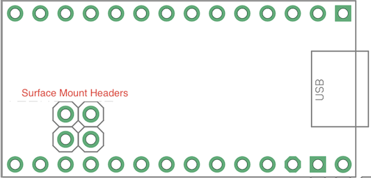
Teensy LC
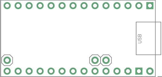
Teensy 4.0
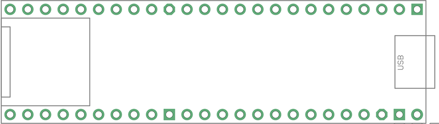
Teensy 4.1