Input / Output API
Defining Pin Types
All pins are represented by a DevicePin object. These are provided by either a secondary device or can be one of the pins directly connected to the microcontroller. For the latter there are some macros with can be used to create the pin objects
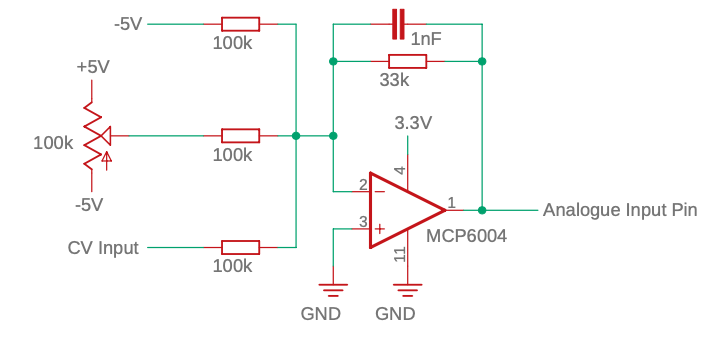
Analog Input
AnalogInput(analogInputPin, A8)
This is a macro which creates an object of type AnalogInputPin<NativeDevice>.
Where analogInputPin is the name of the variable created to represent the pin and A8 is the arduino analog pin number.
Example circuit. Uses an inverting rail-to-rail op-amp powered by 3.3V. Scales an input of -5V/5V to 3.3V/0V required by the Arduino. The values are then re-inverted by the library code. Requires a -5V reference voltage.
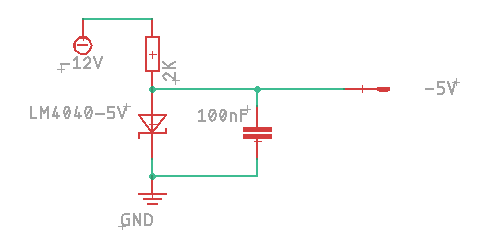
-5V Reference circuit:
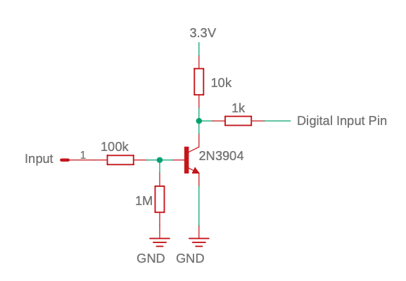
Digital Input
DigitalInput(digitalInputPin, 0)
This is a macro which creates an object of type DigitalInputPin<NativeDevice>.
Where digitalInputPin is the name of the variable created to represent the pin and 0 is the arduino digital pin number.
Example circuit.
Digital Output
DigitalOutput(digitalOutputPin, 1)
This is a macro which creates an object of type DigitalOutputPin<NativeDevice>.
Where digitalOutputPin is the name of the variable created to represent the pin and 1 is the arduino digital pin number.
Analog Input Summing
Two named analog input pins can be summed together using AnalogInputSumPin.
AnalogInputSumPin<> waveSumPin = AnalogInputSumPin<>(wavePotPin, waveCvPin);
Input/Output Modifiers
A pin definition can then be used with a modifier to change the way it behaves. The modifier template requires the type of device that the pin is part of.
If using a direct connection to a microcontroller pin then the default NativeDevice can be used e.g.
LinearInput<> cvInput = LinearInput<>(analogInputPin, -5, 5, 0, 10);
If using an IO expander then it should use the name of the IO expander device:
LinearInput<AnalogInputPin<MAX11300>> cvInput = LinearInput<AnalogInputPin<MAX11300>>(analogInputPin, -5, 5, 0, 10);
Using this system allows us to change hardware without having to do a major refactor of code.
Analog Input Modifiers
LinearInput
Changes the range of the values for an analog input.
LinearInput<> cvInput = LinearInput<>(analogInputPin, INPUT_VOLTAGE_MIN, INPUT_VOLTAGE_MAX, OUTPUT_VALUE_MIN, OUTPUT_VALUE_MAX);
In main loop get value with:
if(potInput.update()) {
    float value = potInput.getValue();
}
ExpInput
Useful for frequency controls and other input that require an exponential response
ExpInput<> pitchInput = ExpInput<>(analogInputPin, MID_VALUE);
MID_VALUE defaults to 523.25 (Frequency of MIDI note C5). Every 1 volt higher doubles the value, every 1 volt lower halfs the value.
AnalogGateInput
Use an analog input like to get a gate signal. Useful if an analog pin can be sometimes used like a gate.
AnalogGateInput<> gateInput = AnalogGateInput<>(analogInputPin, GATE_ON_VOLTAGE);
GATE_ON_VOLTAGE is the voltage above which the gate is considered on. Defaults to 2.0V.
To detect when gate is first triggered on or off:
if(gateInput.update()) {
    if(gateInput.isTriggeredOn()) {

    } else if (gateInput.isTriggeredOff()) {

    }
}
To get current state of gate:
bool trigger = gateInput.isGateOn();
PowInput
TODO
CrossfadeInput
TODO
Digital Input Modifiers
PushButton
A PushButton can be used on a DigitalInput pin. The physcal push button should make a connection between the pin and ground. If the device supports a pullup resistor then this turned on, if not then an external pullup resistor will be needed.
Define:
PushButton<> button = PushButton<>(digitalInputPin);
Use in loop:
if(button.update() && button.pressed()) {
    // Do stuff when button pressed
}
Functions:
button.update()
button.pressed()
button.released()
button.held()
GateInput
TODO
Analog Output Modifiers
TODO
AnalogTriggerOutput
Digital Output Modifiers
TODO
TriggerOutput
TODO
Specialised Hardware
RotaryEncoder
A rotary encoder connected to 2 dgital pins. This currently only works with a direct connection to native device pins and is defined with digital pin numbers.
RotaryEncoder encoder = RotaryEncoder(1, 2);
Needs to be updated in the loop with
encoder.update();
Then the getMovement function will return the amount of movement (negative or positive toindicate direction) since the last update.